Online Powder Bed Fusion 3D Printing Service

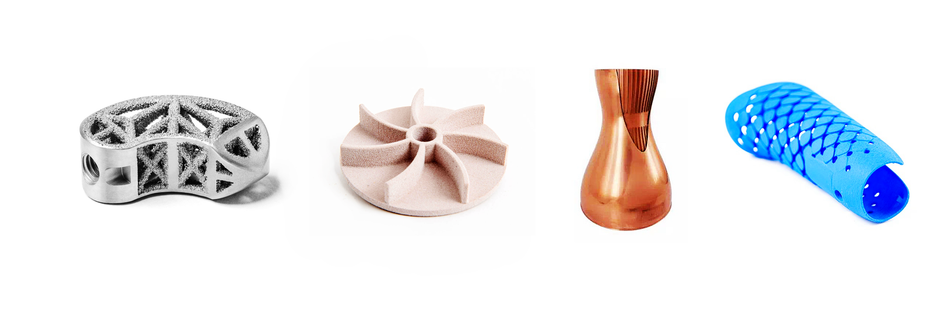
Our Online Powder Bed Fusion 3D Printing Service utilizes Selective Laser Sintering (SLS), Multi Jet Fusion (MJF), Direct Metal Laser Sintering (DMLS), Selective Laser Melting (SLM), and Electron Beam Melting (EBM) technologies. These methods enable high-strength, complex parts with superior material properties for industrial applications and rapid prototyping.
Send us your designs and specifications for a free quotation
All uploaded files are secure and confidential

Benefits of Powder Bed Fusion 3D Printing Service

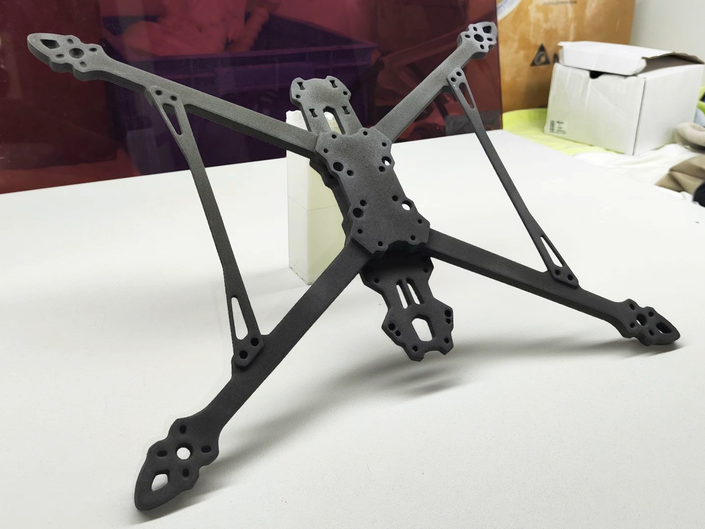
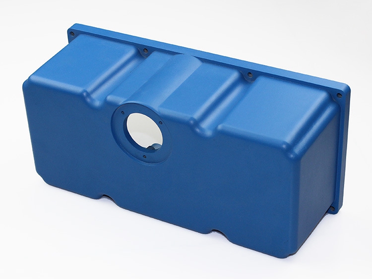
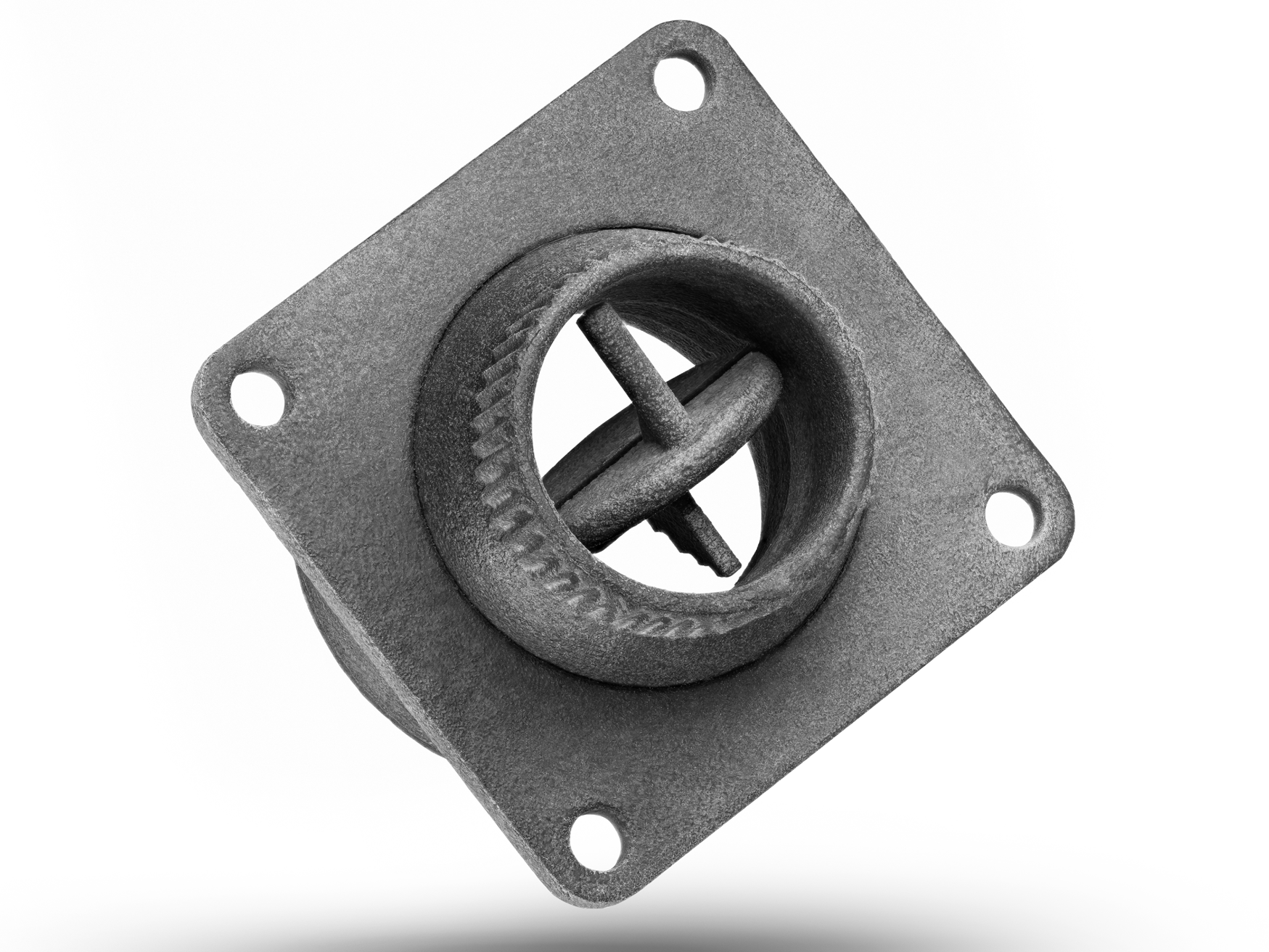
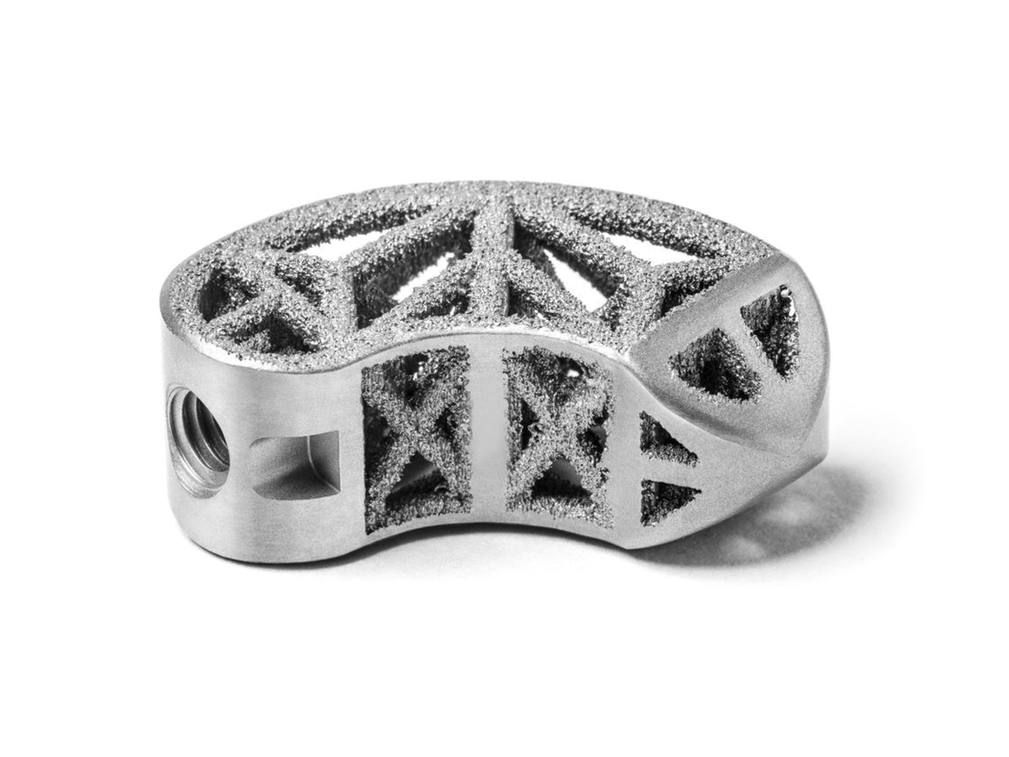
Powder Bed Fusion 3D Printing Service employs a laser or electron beam to fuse powdered material layer by layer. This method produces highly detailed, durable parts with excellent mechanical properties, making it ideal for both prototyping and production of complex components.
Benefits of Powder Bed Fusion 3D Printing Service

Benefits

Description

High Precision and Complexity

Powder Bed Fusion achieves remarkable precision in fabricating complex geometries, enabling the creation of intricate components with fine details. This process supports the production of parts with exceptional dimensional accuracy, meeting stringent design requirements and facilitating the manufacture of advanced, high-performance applications in diverse industries.

Superior Mechanical Properties

The Powder Bed Fusion technique produces parts with superior mechanical properties, offering high strength, durability, and resistance to wear. These robust components meet industrial standards for performance and reliability, making them suitable for demanding applications in aerospace, automotive, medical, and other high-stress environments with excellence.

Material Efficiency

Powder Bed Fusion optimizes material usage by fusing only necessary powder, significantly reducing waste. The unfused powder can be recycled for future builds, promoting sustainable manufacturing practices. This efficient process minimizes cost and resource consumption while maintaining high-quality production standards consistently, ensuring optimal material performance.

Design Freedom

Powder Bed Fusion offers design freedom by enabling the production of complex internal structures and geometries that traditional methods cannot achieve. This capability fosters innovation and customization, allowing designers to create lightweight, intricate parts that optimize performance while pushing the boundaries of conventional manufacturing limitations.

SLS Vs. MJF Vs. DMLS Vs. SLM Vs. EBM

This comparison outlines the differences between Selective Laser Sintering (SLS), Multi Jet Fusion (MJF), Direct Metal Laser Sintering (DMLS), Selective Laser Melting (SLM), and Electron Beam Melting (EBM) in terms of technology, materials, strength, accuracy, speed, surface finish, machine costs, and applications.

Aspect

SLS

MJF

DMLS

SLM

EBM

Technology

Uses a laser to sinter powdered material layer by layer.

Uses an inkjet array to apply fusing agents to powder layers, then fuses them with heating elements.

Similar to SLS but specifically for metal powders.

Uses a high-power laser to fully melt metal powders.

Uses an electron beam to melt metal powder.

Materials

Nylon, polymers, ceramics, glass, etc.

Nylon and other plastics, offering controlled properties and colors.

Metals like steel, titanium, and aluminum alloys.

Metals including steel, titanium, aluminum, and cobalt chrome.

Titanium, cobalt chrome, and other high-strength metals.

Strength

High strength, durable parts; slightly less dense than bulk material.

Produces parts with nearly isotropic properties, generally stronger than SLS.

Parts have properties comparable to wrought metals.

Parts are very strong and fully dense.

Produces parts that are extremely strong and stress-relieved.

Accuracy

High dimensional accuracy with a slightly rough surface texture.

High accuracy with smoother surfaces compared to SLS.

High precision, suitable for complex metal parts.

Very high accuracy, ideal for complex geometries and thin walls.

High accuracy, especially for complex internal geometries.

Speed

Relatively fast; no need for support structures.

Faster than SLS due to simultaneous layer processing.

Slower, due to precision and power requirements for sintering metals.

Slower, as complete melting of metal requires more energy.

Generally faster than SLM due to rapid scanning speed of the electron beam.

Surface Finish

Slightly rough; may require post-processing for smoothness.

Generally smoother than SLS; minimal post-processing required.

Can be rough; often requires post-processing.

Smooth finish; minimal post-processing compared to DMLS.

Similar to SLM; smooth with minimal post-processing.

Machine Costs

Moderate, accessible for industrial applications.

Generally higher than SLS due to advanced technology.

High, due to complexity and safety requirements for handling metals.

High, similar to DMLS; requires precise control and safety measures.

High, requires vacuum environment and complex controls.

Applications

Functional prototypes, complex geometries, production parts.

Ideal for functional parts needing high detail and durability.

Aerospace, automotive, medical implants.

Aerospace, automotive, high-stress environments.

Aerospace, orthopedic implants, parts requiring high strength and precision.

Let's Start A New Project Today

Powder Bed Fusion 3D Printed Parts Design Guideline

These design guidelines for powder bed fusion help optimize part performance by addressing critical aspects such as feature size, wall thickness, supports, orientation, and more. Following these recommendations improves precision, structural integrity, and overall print quality.

Design Aspect

Guideline

Reasoning

Minimum Feature Size

Typically 0.5 mm or greater

Ensures that small features are robust enough to be built and remain intact.

Wall Thickness

Minimum of 0.8 mm; recommended 1 mm or greater

Thinner walls may not fully fuse or could be too fragile to handle post-processing.

Supports

Often required for overhangs greater than 45° and large spans

Supports stabilize the structure during printing and prevent warping.

Orientation

Optimize to reduce the need for supports and minimize exposure to the heat source

Reduces post-processing and potential distortions due to heat stress.

Escape Holes

Include for enclosed and hollow parts to allow powder removal

Ensures that unsintered powder can be removed from complex internal cavities.

Clearance

Minimum of 0.5 mm for parts intended to fit together

Compensates for powder fusion inconsistencies and ensures proper fit post-processing.

Layer Thickness

Typically ranges from 20 to 100 microns

Finer layers yield better surface finish and detail but increase build time.

Post-Processing

Necessary for surface finishing and to improve mechanical properties

Powder bed fusion often leaves a rough surface that requires smoothing.

Aspect Ratio

Keep aspect ratio low for unsupported features

High aspect ratios may lead to failure during build due to insufficient support.

Infill

Solid infill isn't always necessary; strategic use can save material and time

Using less than solid infill can reduce weight and material usage without compromising strength.

Surface Quality

Bottom surfaces in contact with powder may differ from top surfaces

Powder-contact surfaces might be rougher and require post-processing.

Thermal Distortion

Consider the effects of localized heating and cooling

Designs should minimize large cross-sectional areas to reduce thermal distortion.

Tolerance

Expect ±0.1 to ±0.3 mm depending on material and machine

Accounts for thermal expansion and variability in powder particle size.

Frequently Asked Questions

Explore Related Resources