Online Material Extrusion 3D Printing Service

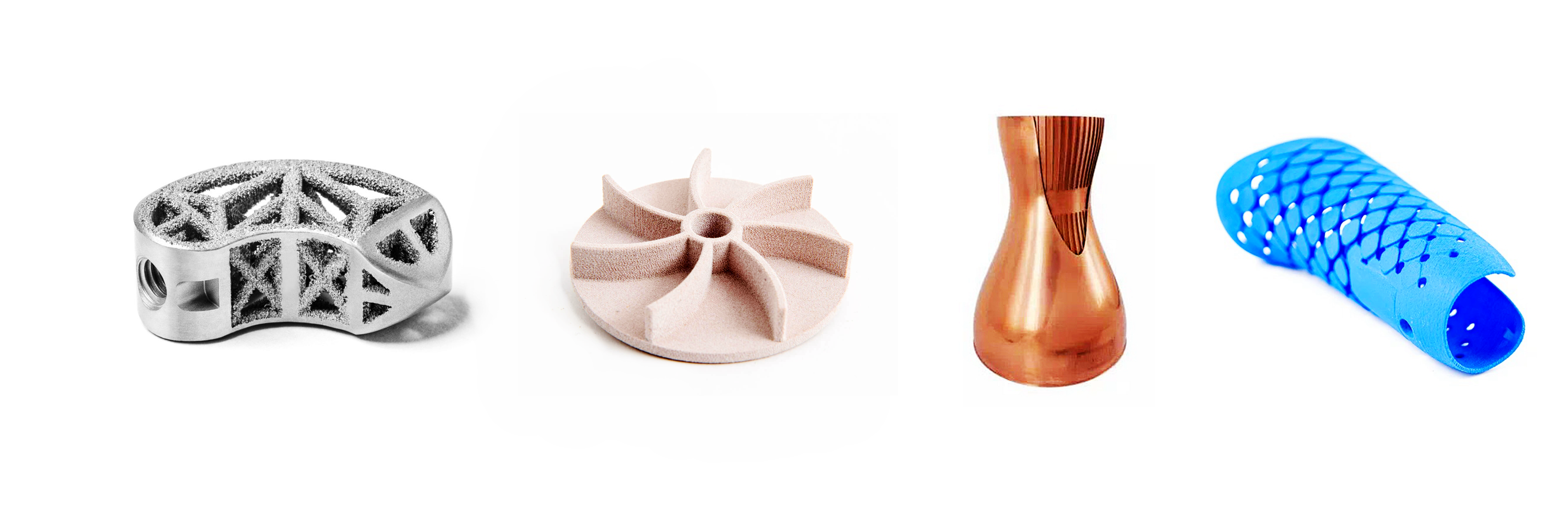
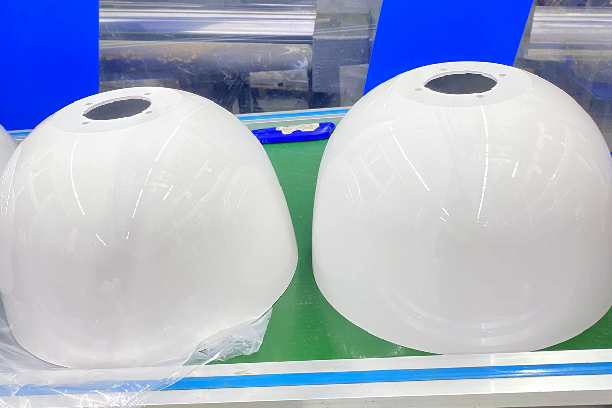
Our Online Material Extrusion 3D Printing Service utilizes Fused Deposition Modeling (FDM) and Fused Filament Fabrication (FFF) to produce durable, precise parts. These methods offer rapid prototyping, customizable designs, and a wide range of materials, ideal for functional prototypes, low-volume production, and complex geometries at competitive prices.
Send us your designs and specifications for a free quotation
All uploaded files are secure and confidential

Benefits of Material Extrusion 3D Printing Service

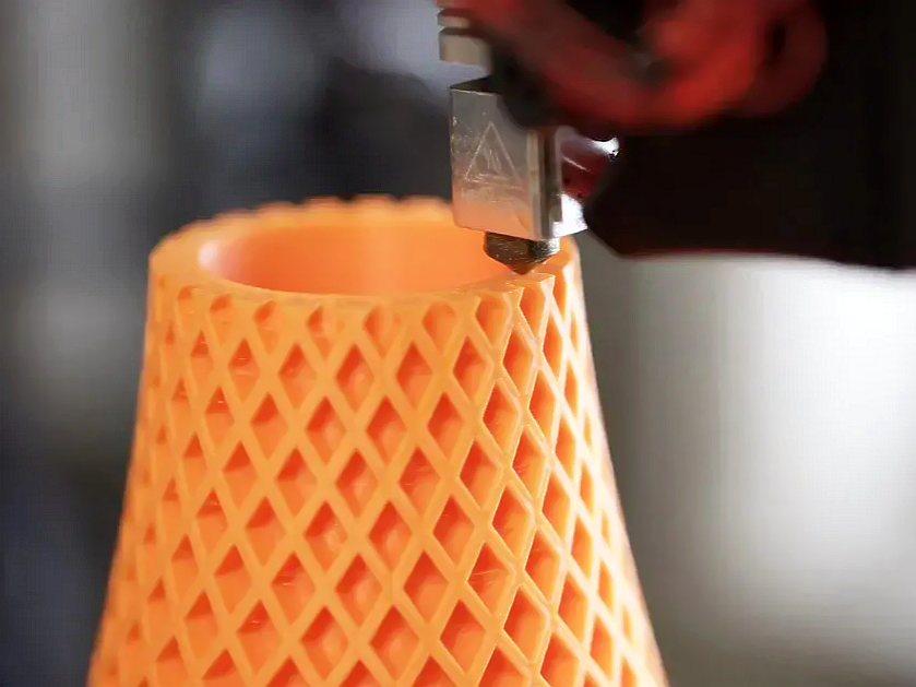
Material Extrusion 3D Printing Service uses a heated nozzle to extrude and deposit thermoplastic materials layer by layer. Commonly known as Fused Deposition Modeling (FDM), it is cost-effective and ideal for prototyping, functional parts, and low-volume production. It supports materials like PLA, ABS, PETG, and composites for diverse applications.
Benefits of Material Extrusion 3D Printing Service

Benefits

Description

Cost-Effectiveness

Material Extrusion is generally more affordable than other 3D printing technologies, both in terms of initial setup (equipment cost) and operating costs (material and maintenance). This makes it accessible for hobbyists, small businesses, and educational settings.

Material Versatility

Supports a wide range of materials, including various thermoplastics like PLA, ABS, PETG, and specialty composites infused with metals, wood, or carbon fiber. This versatility allows users to select materials based on specific property requirements such as strength, flexibility, or thermal stability.

Ease of Use

The technology is relatively easy to use and understand, making it suitable for beginners and professionals alike. Many desktop 3D printers operate on this technology, which has a straightforward process of printing layer by layer from digital files, often with user-friendly software interfaces.

Customization and Complexity

Allows for high customization and complexity without significantly impacting the cost, enabling the creation of bespoke items or intricate designs that would be difficult or expensive to produce using traditional manufacturing techniques. This benefit is crucial for prototyping, custom tools, and unique product designs.

Comparison Of FFF and FDM

This comparison outlines key aspects of Fused Deposition Modeling (FDM) and Fused Filament Fabrication (FFF), including definitions, trademark status, process details, materials, applications, printer availability, cost, community support, and innovation.

Aspect

Fused Deposition Modeling (FDM)

Fused Filament Fabrication (FFF)

Definition

A 3D printing process that uses a continuous filament of thermoplastic material.

Same as FDM, but the term FFF is used to avoid trademark issues with the term FDM.

Trademark

Trademarked by Stratasys in 1991.

A term coined by the RepRap community to be used freely without trademark restrictions.

Process

Material is extruded through a heated nozzle, deposited layer by layer to build an object.

Identical process: extrusion of thermoplastic material through a heated nozzle to build an object layer by layer.

Materials

Typically uses proprietary filament spools like ABS, PLA, PETG, Nylon, etc.

Uses a wide range of standard filament types, often less expensive due to its non-proprietary nature.

Applications

Used for prototyping, educational purposes, and manufacturing end-use parts.

Same applications: prototyping, education, and production of functional parts.

Printer Availability

Predominantly available from commercial manufacturers like Stratasys.

Widely available from various manufacturers, with many open-source designs.

Cost

Generally higher due to proprietary materials and machine costs.

Typically lower, benefiting from open-source contributions and competitive pricing.

Community Support

Supported by commercial services.

Extensive community support with forums, DIY guides, and modifications.

Innovation

Innovations may be slower due to proprietary restrictions.

Rapid innovation driven by open-source contributions and less restrictive experimentation.

Let's Start A New Project Today

Material Extrusion 3D Printed Parts Design Guideline

These design guidelines help optimize parts for material extrusion 3D printing by addressing critical aspects such as wall thickness, overhangs, supports, and more. Following these recommendations can improve part strength, accuracy, and overall print quality.

Design Aspect

Guideline

Reasoning

Wall Thickness

Minimum of 0.8 mm; recommended 1.2 mm or greater

Thinner walls may not be strong enough and could fail during printing or in use.

Overhangs

Limit to 45 degrees or support structures must be used

Overhangs greater than 45 degrees can sag or collapse without support.

Supports

Design parts to minimize the need for supports wherever possible

Supports add to material usage and post-processing time, increasing costs.

Orientation

Optimize orientation for the least amount of support and best surface finish

Orientation affects the strength and appearance of the part, as well as print time.

Bridging

Keep bridges short, ideally less than 5 mm

Longer bridges can sag without support, affecting the quality of the part.

Holes

Design holes larger than 2 mm in diameter; for smaller, consider post-processing

Small holes can close up or become deformed due to material flow and cooling rates.

Infill

Use higher infill for areas requiring more strength

Higher infill increases part strength but also material usage and print time.

Layer Height

Typically between 0.1 mm and 0.3 mm

Smaller layer heights improve surface finish but increase print time.

Top/Bottom Thickness

Minimum of 0.6 mm; recommended 1.2 mm or greater

Ensures the top and bottom of the part are solid and well-formed.

Corners

Consider adding fillets or chamfers to sharp corners

Reduces stress concentrations and the likelihood of delamination.

Enclosures

Ensure adequate clearance for assembly, typically add at least 0.5 mm

Allows for easier assembly and accounts for slight size variations in printed parts.

Detail Resolution

Minimum feature size of 0.8 mm

Smaller features may not be accurately reproduced due to nozzle size limitations.

Tolerance

Typically ±0.5 mm, can vary based on part geometry and size

To account for the inherent variability in the printing process and material behavior.

Frequently Asked Questions

Explore Related Resources